![Logo AttriX Bleu.svg]](https://support.attrix.ca/hubfs/Logos/AttriX/Logo%20AttriX%20Bleu.svg)
4.2 Surface Mounting
Two surface mounting options are available: screws or VHB
4.2.1 Screw Mounting
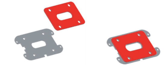
- Use the surface mounting plate as a template to mark the installation location of the ST 2100. Ensure hole positions are marked.
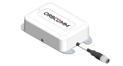
- Route the cord through one of the two cable channels.
- Install the silicone plug in the unused cable channel.
- Attach the mounting plate onto the ST 2100 using the four (4) countersunk screws (see figure above) applying a torque of 1 N-m (8.5 in-lbs).
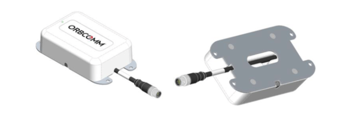
- Position the assembled ST 2100 at the marked installation location, then use the four (4) hex head screws to secure the ST 2100 to the equipment.
CAUTION: Do not use VHB adhesive tape on the mounting plate.
CAUTION: Do not over tighten screws.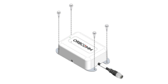
4.2.2 VHB Mount Installation.
- Before starting installation, read the important weather-related guidelines in ANNEX B.
- Ensure both the mounting surface and the VHB tape are at a temperature of at least 15°C (60°F). If necessary, use a heat lamp or heat gun to warm them up.
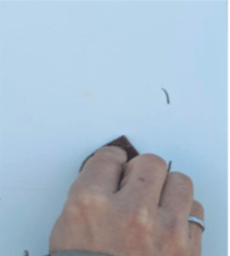
- Use the provided surface preparation pad to lightly scratch the surface of the asset at the mounting location.
- Use the provided alcohol pad to clean the mounting surface. Ensure the area is free of any dirt or particles. Clean the surface using alcohol cleaner or a wipe.
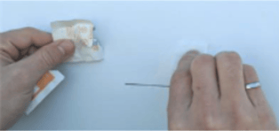
- Press the provided primer tube to crush the insert and release the primer, then apply the primer to the mounting surface. Apply primer to the surface, then wait at least 30 seconds for the primer to dry.
- Use the surface mounting plate as a template to mark the installation location of the ST 2100.
- Remove one of the liners from the VHB pad, then affix it to the cleaned mounting plate ensuring that the screw holes on both surfaces align and air bubbles are minimized.
CAUTION: Do not touch the VHB tape.
CAUTION: VHB tape installation temperature must be above 15°C (60°F). See ANNEX B. - Route the ST 2100 pigtail through one of the two cable channels.
- Install the silicone plug in the unused cable channel.
- Attach the mounting plate/VHB pad onto the ST 2100 using the four (4) countersunk screws (see figure above).
CAUTION: Do not over tighten screws. - Carefully remove the second liner to attach the ST 2100 to the asset.
- Position the assembled ST 2100 at the marked installation location.
- Firmly press down on the entire top surface of the ST 2100 (15 pounds for 60 seconds) to bond the VHB to the asset.
5 POWERING ON AND REGISTERING THE ST 2100
When powering on the device, the ST 2100 enters satellite search mode to acquire the IsatData Pro network. This activity may take a few minutes. The ST 2100 must complete registration to operate.
Once the ST 2100 synchronizes with the network, it sends a registration message to the IsatData Pro network. The ST 2100 will not register until it has a clear line of sight to the satellite. The IsatData Pro network records the registration message and transmits it to the user's application. The IsatData Pro network sends an acknowledgment message to the ST 2100 via the satellite. The ST 2100 is now available to send and receive messages via satellite.
- Before connecting the ST 2100 to an external power source, ensure polarity is correct and the voltage source is between 9 and 32 VDC. Refer to the connector pin assignment description.
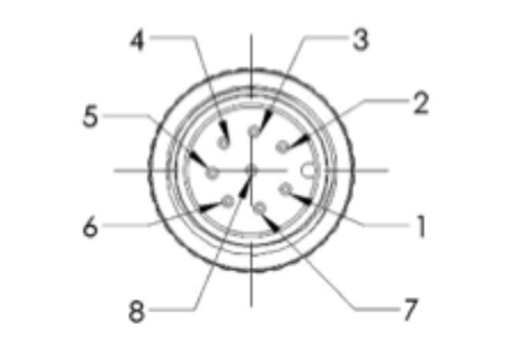
| Pin | Colour | Description |
| 1 | White | External Reset Input |
| 2 | Brown + | Ground |
| 3 | Green | RS-232 Rx (Input) |
| 4 | Yellow | RS-232 Tx (Output) |
| 5 | Grey | VEXT (9-32 VCD External power supply) |
| 6 | Pink | 1 PPS Output |
| 7 | Blue | Event Notification Output |
| 8 | Red | External Reset Output |
2. Ground the plug simultaneously or before powering on the device.
3. Check the ST 2100 indicator light to ensure it has been powered on. The visual indicator (LED) does not indicate satellite status. Its sole purpose is to confirm that the ST 2100 is powered.