![Logo AttriX Bleu.svg]](https://support.attrix.ca/hubfs/Logos/AttriX/Logo%20AttriX%20Bleu.svg)
Installation Guide Orbcomm ST9100
1.2.1 Shipping Box Contents
Unpack the contents of the shipping boxes, then use the list below as a guide to check that you have received the items you ordered.
- ST 9100 (p/n ST9100-D01 for use in the Americas, and ST9100-C01 for use outside the Americas)
- Power and I/O Connector (p/n ST101096) or blunt cut cable assembly (p/n ST101062-002)
- Cellular antenna with FAKRA connector (p/n ST101066-001)
- Satellite antenna with FAKRA connector (p/n ST901065-APA standard antenna, ST901066-APA low elevation antenna)
- Terminal cover (optional - p/n ST101014-001)
1.2.2 Additional Hardware
Installation of a transceiver may require some of the following items. These materials are not included with the terminal.
If mounting the transceiver and antenna on a mounting surface, you will need:
- Qty. 4 - Stainless steel #8 fasteners (for transceiver or terminal cover)
- Qty. 4 - Stainless steel M4 fasteners (for satellite antenna)
Refer to Appendix G for more details regarding the blunt cut cable.
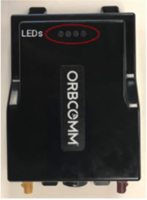
1.2.5.2 Location and Operation of LEDs
The transceiver features four visible LEDs (Figure 5) indicating its status.
Figure 5: LED Locations
| Icons | Indicator | Description |

|
Sensor | Indicates whether the terminal is receiving sensor data or paired with a sensor. |

|
Cellular | Indicates the status of cellular communications. |
|
|
Satellite | Indicates the status of satellite communications. |

|
Power | Indicates the transceiver has external power. |

1.3 Determining an Appropriate Mounting Location
Before installing the transceiver, consider the important guidelines provided below.
WARNING: Most users install the ST 9100 in a vehicle. It is crucial that installers securely and safely mount the ST 9100 to avoid any danger or damage to individuals or property.
WARNING: Do not install or operate the device near flammable gases or fumes.
- Mount indoors, inside a vehicle, or in a location sheltered from environmental elements. If mounting outdoors, use a terminal cover.
- Securely fasten the transceiver so it does not come loose or move easily.
- Mount the transceiver on a surface whose temperature does not exceed the maximum operating temperature. If the surface may become hotter, mount the transceiver with a thermal barrier between it and the mounting surface.
- Do not mount the transceiver near other electrical equipment due to potential radiated and/or conducted electromagnetic interference. Do not mount the transceiver where water or ice could accumulate or deposit.
- Ensure the transceiver cable reaches the power source before drilling mounting holes.
- Do not mount the transceiver near radar antennas or other communication antennas. Follow the guidelines below:
> 1 m (39 in) from VHF/UHF
> Antenna 3 m (10') from loop
> antenna 4 m (13') from MF/H
> antenna 5 m (16') from other satellite antennas
Not in radar beam
- Mount the transceiver on a flat surface, parallel or perpendicular to the ground, to ensure proper operation of the internal accelerometer.
Once you have chosen the mounting location, proceed to mount the transceiver.
1.3.1 Guidelines for Mounting a Standard Satellite Antenna
WARNING: Mount the antenna at least 25 cm away from people.
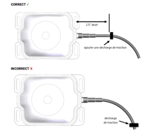
WARNING: Cable management and connector strain relief must be integrated into the installation. Ensure the cable runs straight for at least the first 64 mm (2.5 in.), then secure it shortly after this point and at regular intervals along its length within the installation framework to prevent cable wear and eliminate tension on the transceiver connector. Otherwise, damage to the transceiver connector interface or cable may result in hardware failure.
- Do not drill any holes until you have verified that you have sufficient space for the antenna cable bend radius. For reliable operation, do not go below a bend radius of 1.5 cm (0.6 in.). Measure the cable bend radius as shown in Figure 6.
Figure 6: Antenna Cable Bend Radius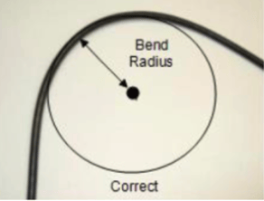
- Mount on a surface free of dirt, grime, water, and grease to avoid damaging the mounting surface or vehicle paint.
- Mount so that the cable end is oriented towards the rear of the vehicle.
- For fixed installations, ensure the satellite antenna is oriented towards the equator, south if in the northern hemisphere and north if in the southern hemisphere, and its line of sight to the sky (satellite) is clear of any obstructions.
- For mobile installation, mount the antenna at the highest point on the vehicle or boat, where it has a clear view of the sky (satellite) in all directions.
1.3.2 Guidelines for Mounting Cellular Antennas
- Mount indoors, for example, inside a vehicle window, near the transceiver unit
- Mount on a flat surface for maximum adhesion.
- Mount at least 2 cm away from metal objects.
- Mount the cellular antenna at least 1 m (39 in) away from the satellite antenna.
1.4 Mounting Antennas
The transceiver operates with a satellite antenna and/or a cellular antenna (section 1.4.3). Two mounting options are available for the satellite antenna: screw mount (section 1.4.1) or cable tie mount (section 1.4.2).
1.4.1 Screw Mount
- For mounting an antenna, the following tools and materials are required: Drill
- M4 hardware
- Outdoor sealing adhesive (silicone)
To mount the antenna, follow the steps below.
- Find a location for the antenna following the instructions in section 1.3.
- Use the mounting template (Appendix B) or the antenna as a template to mark the mounting hole locations.
WARNING: Cable management and connector strain relief must be integrated into the installation. Ensure the cable runs straight for at least the first 64 mm (2.5 in.), then secure it shortly after this point and at regular intervals along its length within the installation framework to prevent cable wear and eliminate tension on the transceiver connector. Damage to the transceiver connector interface or cable may result in hardware failure. 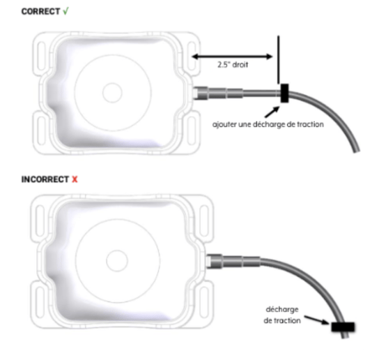 Drill the holes using a drill.
- Apply a sealing product, such as RTV silicone, around the drill holes to prevent water from entering the active element.
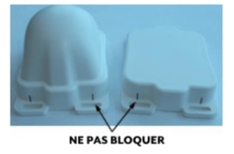
WARNING: Do not obstruct the ventilation holes (two locations). - Secure the antenna in place using self-tapping screws or mechanical screws and nuts, depending on access to the mounting surface.
1.4.3 Cellular Antenna
- Clean the antenna mounting surface with isopropyl alcohol to remove any dirt residue. Ensure the surface is dry before applying the antenna adhesive tape.
- Remove the adhesive tape from the cellular antenna.
- Mount the cellular antenna inside the window. Figure 10 shows examples of mounting on an automobile.
Figure 10: Examples of cellular system mounting locations - example
- Secure the cellular antenna cable in place.
1.5 Routing the Main Cable
Consider the following guidelines before routing all cables.
WARNING: Ensure that the power cable is not pinched, bent, or worn by objects or moving parts such as door hinges. It is very important to secure the cable at many points along its path.
WARNING: Before any intervention on the wiring, ensure that the transmitter-receiver is powered off and cannot start during the intervention.
- Do not route the cable near the engine if it passes through the engine compartment. This location exposes the cable to extreme heat.
- Keep the cable away from hot surfaces such as exhaust pipes as this could damage the cable.
- Do not route the cable over sharp or serrated edges.
- Place the cable in recesses and channels, where possible, to avoid any potential damage or wear from pedestrian traffic.
Note: Don't forget to leave enough slack in the cable near the transmitter-receiver for strain relief to avoid introducing additional force on the connector. ORBCOMM recommends securing the cables during installation.
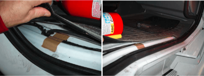
Figure 11: Example of cable placement in a vehicle cabin.
WARNING: Cable management and strain relief of connectors must be integrated into the installation. ORBCOMM strongly recommends securing the cable at regular intervals along its length as part of the installation to prevent cable wear and eliminate tension on the connector. Failure to do so could result in damage to the connector interface or cable and lead to hardware failure.
- Apply adhesive tape around the cable ends to facilitate its routing.
- Secure the cable in a manner that does not pull on the connector or exert strain on the transmitter-receiver connector.
- Fasten the cable so that the weight of a vibrating cable does not stress the connection.
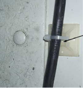
- Attach the cable using clamps and cable ties (Figure 12) at intervals of 30 to 60 cm (12 to 24 inches) along the cable path to prevent rubbing, wear, or strain.
- Secure the cable tie with a self-tapping screw (Figure 12) to ensure better retention of the cable tie.
Note: The solution provider is required to provide mounting instructions if the mounting is to be done using tools or configurations different from those described in this document.
Note: The installer is responsible for compliance with local electrical codes.
WARNING: Cable management and strain relief of connectors must be integrated into the installation. ORBCOMM strongly recommends securing the cable at regular intervals along its length as part of the installation to prevent cable wear and eliminate tension on the connector. Damage to the connector interface or cable may result and lead to hardware failure.
- Connect the satellite antenna to the yellow FAKRA connector of the transmitter-receiver by pressing until you hear a click.
WARNING: Only use antennas of the same color.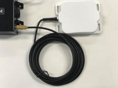
- Connect the cellular antenna to the purple FAKRA connector of the transmitter-receiver by pushing until you hear a click.
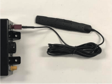
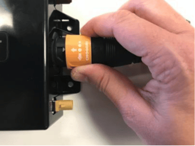
- Connect the power cable and the I/O cable to the transmitter-receiver by pushing and twisting until it clicks into place.
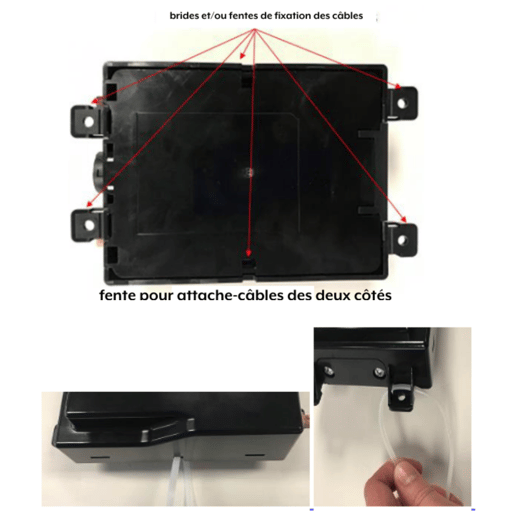
1.6.2 Transmitter-Receiver Mounting
CAUTION: Skip this step if using a terminal shroud.
- Review mounting guidelines before securing the transmitter-receiver permanently.
- Mount the transmitter-receiver using cable ties or washers and screws. Cable ties can be used if the transmitter-receiver remains flat and is parallel or perpendicular to the ground, to ensure proper operation of the internal accelerometer. Otherwise, secure the transmitter-receiver to a rigid surface using washers and screws. Use the holes to mark and drill pilot holes according to the type of screws. The transmitter-receiver is surrounded by multiple flanges or locations for cable ties.
1.7 Power Connection
WARNING: Only power on the device after grounding has been completed.
WARNING: Before powering the transmitter-receiver, ensure that the nominal voltage of your power supply complies with the recommended values. Refer to [T413] for more details. WARNING: The installer is responsible for compliance with local electrical codes.
Note: ORBCOMM recommends waiting, if possible, for the terminal to be unlocked (with a clear view of the sky) before powering on the transmitter-receiver.
- Locate the main power input and ground (GND) wires using the connector pinout table (APPENDIX E). You can connect the transmitter-receiver ground to the fuse panel ground or the chassis ground. To do this, attach the ground wire of the cable to a piece of metal electrically connected to the vehicle chassis using a sheet metal screw.
- Ensure that the main power input and ground wires reach the vehicle's fuse panel. If the wires are not long enough, splice wires of the same gauge to the main power input and ground wires so that they reach the fuse panel. Cover all splices with adhesive-lined heat shrink tubing.
- Connect the connectors properly before powering on the device.
- Connect the ground wire to the selected grounding point as determined in a previous step. Ensure correct polarity and that the voltage source is within 9-32 VDC.
- Connect the main power input wire to the unswitched power source of the vehicle in the fuse panel.
- Secure any excess wiring and loop it neatly.
1.9 Registering the terminal
1.9.1 Terminal Activation
Upon power-up, the terminal enters satellite search mode to acquire the IsatData Pro network. This process may take a few minutes. Terminals must complete registration to operate.
Once the terminal synchronizes with the network, it sends a registration message to the IsatData Pro network. The terminal will not register until it has a clear line of sight to the satellite.
The IsatData Pro network records the registration message and transmits it to the user's application. The IsatData Pro network sends an acknowledgment message to the terminal via the satellite. The terminal is now available to send and receive messages via satellite.
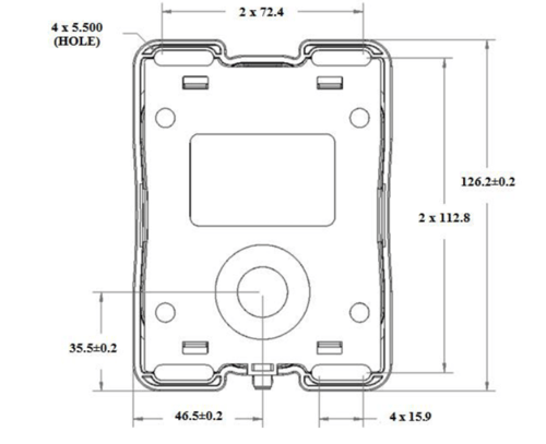
Annexe B...
WARNING: Before drilling, verify the accuracy of the template dimensions against the actual hardware. If they do not match, DO NOT USE THIS TEMPLATE. Use the physical antenna hardware as a template.
WARNING: Cable management and strain relief of connectors must be integrated into the installation. Ensure that the cable exits straight for at least the first 64 mm (2.5 in.), then secure it shortly after this point and at regular intervals along its length as part of the installation to prevent cable wear and eliminate tension on the connector. Otherwise, the connector interface or the cable may be damaged and lead to hardware failure.
Note: Dimensions are provided in millimeters.
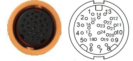
ANNEXE E PIN CONNECTIONS
Table 1 corresponds to the arrangement shown in Figure 19
Figure 19: Connector Cable View
| PIN | Fonction | Type | Description |
| 1 | RS485_A | I/O | Diverter output or semi-duplex RS485 receiver input (complementary to RS485_B) |
| 2 | Digital_IN4 / 0-5 V_IN4 | I | Digital input or 0-5 V analog input |
| 3 | Digital_IN3 / 0-5 V_IN3 | I | Digital input or 0-5 V analog input |
| 4 | I/O_4 | I/O | Multifunctional GPIO, push-pull, analog input, limited current sink, or ignition load |
| 5 | I/O_2 | I/O | Multifunctional GPIO, push-pull, analog input, or current sink |
| 6 | GROUND | PWR | External power ground return |
| 7 | External Voltage | PWR | External power supply 9-32 VDC |
| 8 | Sortie_6 | O | Open-drain output |
| 9 | 1Wire Com | PWR | 1-Wire return path |
| 10 | Console_RS232_TX | O | Transmission port signals: ±15 kV electrostatic discharge protected, RS-232 levels (typically ±5.5 V) protected up to ±25 V. Receiver inputs. |
| 11 | AUX_RS232_RX | I | Reception port signals: ±15 kV electrostatic discharge protected, RS-232 levels (typically ±5.5 V). Transmitter outputs. |
| 12 | CAN1_H | I/O | High-level CAN BUS line |
| 13 | CAN1_L | I/O | Low-level CAN BUS line |
| 14 | CAN0_L | I/O | Low-level CAN BUS line |
| 15 | RS485_B | I/O | Pilot output or semi-duplex RS485 receiver input (complementary to RS485_A) |
| 16 | Digital/Analog_IN1 / 0-5 V_IN1 / P1_4-20 mA+ | I | Digital input or 0-5 V analog input or 4-20 mA input |
| 17 | I/O_3 | I/O | Multifunctional GPIO, push-pull, analog input, or current sink |
| 18 | I/O_1 | I/O | Multifunctional GPIO, push-pull, analog input, or current sink |
| 19 | Output_5 | O | Open-drain output |
| 20 | 1Wire_DATA | I/O | Input/output pilot for 1-wire line |
| 21 | Console_RS232_RX | I | Reception port signals: ±15 kV electrostatic discharge protected, RS-232 levels (typically ±5.5 V). Transmitter outputs |
| 22 | AUX_RS232_TX | O | Transmission port signals: ±15 kV electrostatic discharge protected, RS-232 levels (typically ±5.5 V) protected up to ±25 V. Receiver inputs |
| 23 | CAN0_H | I/O | High-level CAN BUS line |
| 24 | Digital_IN2 / 0-5 V_IN2 / P2_4-20 mA+ | I | Digital input or 0-5 V analog input or 4-20 mA input |