![Logo AttriX Bleu.svg]](https://support.attrix.ca/hubfs/Logos/AttriX/Logo%20AttriX%20Bleu.svg)
IOX-SATIRDv2 "Satellite IRIDIUM"
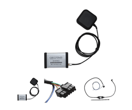
If a vehicle is in an area without cellular or network connection, the Iridium® satellite modem allows the Geotab® GO™ device to communicate using the Iridium network. The IRIDIUM Satellite modem of the IOX-SATIRDv2 enables the GO device to communicate via the IRIDIUM network, allowing users to track their fleet even in case of connection loss.
Installation Video
Alert Button Notification
The IOX-SATIRDv2 allows the driver to send a priority emergency message to MyGeotab® via the satellite network using an alert button (not included). For further information, refer to step 8 of the installation instructions.
IOX Hardware Technical Specifications Weight
| Weight | 70 g |
| Size |
Total length: 1810 mm Widest point: 31 mm × 16 mm |
| Enclosure | PC+ABS shell enclosure |
| Interfaces |
CAN: 500 kb/s; for serial mounting RS-232 serial interface |
| Inputs | Emergency switch line: open — grounded |
| Nominal input voltage | 12 V / 24 V |
| Output power | IRIDIUM interface: 900 mA at 12 V/24 V |
|
Current draw IOX-SATIRDv2 on GOx serial mount |
40 mA at 12 V / 24 V Operating mode (typical/nominal current draw) 100 mA at 12 V / 24 V Operating mode (maximum current draw) 0.4 mA at 12 V / 24 V Standby mode (minimum current draw) |
| Temperature rating | -40 ℃ to +85 ℃ |
| Connectors |
Iridium satellite antenna connector: SMA male plug Iridium satellite modem connector: SMA female socket Type B male mini-USB connector: chain power and CAN enabled Type B female mini-USB connector: chain power and CAN disabled 12-pin Molex connector 43025-1200: IRIDIUM modem
|
| Installation |
|
| Compatible Devices | All GO7® and later devices and its variants |
| GO9 can provide a maximum total current to IOX in series. |
2,500 mA at 12 V/24 V Note: For each IOX in series, add the maximum current draw and do not exceed the total maximum current draw of IOX. |
IOX Installation Instructions
✱ NOTE: Installation must be performed by a professional — Installation of the IOX-SATIRDv2 requires the installer to have sufficient knowledge and technical expertise for installing and integrating mobile devices inside modern vehicles (i.e., Certified Geotab® installer or equivalent).
WARNING! Before installing the IOX-SATIRDv2, read and follow the GO device installation instructions (goo.gl/bgnwaK) to ensure proper installation of the GO device in preparation for the installation of the IOX-SATIRDv2. Improper installation of the GO device or the IOX-SATIRDv2 can result in loss of vehicle control and serious injury.
WARNING! Before installing the IOX-SATIRDv2, read and follow the important safety information, including usage limitations, found following these installation instructions. Always read and adhere to safety information to avoid loss of vehicle control and serious injury.
Mandatory Process for IOX-SATIRDv2 Device Management
- Mandatory activation required – The Iridium satellite modem must also be activated 24 hours prior to installation. To request activation, you must create a technical support ticket stating in the subject line of the ticket: IOX-SATIRDv2 activation request (IOX-SATIRDv2 activation request). You must also include the GO device serial number and the IRIDIUM IMEI number on the ticket.
- To request deactivation of an Iridium satellite modem, submit a support ticket with the following subject: IOX-SATIRDv2 deactivation request (IOX-SATIRDv2 deactivation request). You must include the GO device serial number and the Iridium IMEI identifier in the ticket.
✱ NOTE: Disconnecting or suspending a GO device does NOT automatically deactivate the connected Iridium modem. Please submit a support ticket to request deactivation of the Iridium modem.
- If an Iridium satellite modem needs to connect to another GO device, please create a support ticket with the following subject: IOX-SATIRDv2 pairing change. You must include the Iridium IMEI identifier and the serial number of the new GO device in the ticket.
How to Install IOX-SATIRDv2
| 1 | Start with the Geotab GO device disconnected from the vehicle. Remove the blue cover from the IOX expansion port of the GO device. |
| 2 |
Plug the IOX's 90° USB connector into the GO device. Secure the USB connector using a cable tie, being careful not to overtighten to avoid damaging the USB connector. ✱ NOTE: The USB connector can only be inserted in one direction (see image). |
| 3 |
Choose a suitable location to install the IOX-SATIRDv2. ✱ NOTE: Remember that the location you choose to install the GO device will influence the available location to install the IOX-SATIRDv2 due to wire length. Installation should not interfere with safe vehicle operation. |
| 4 |
The IRIDIUM satellite antenna has a magnetic base and a double-sided adhesive ring under the antenna for installation on plastic surfaces. The antenna location should not interfere with safe vehicle operation or obstruct the driver's view outside the vehicle in any way. WARNING! Superstructure equipment transmits radiofrequency (RF) energy that can cause thermal injuries, including tissue damage due to increased heat and body temperature. When the system is powered on, keep all personnel at least 1 m (3.3 ft) away from the antenna. Failure to comply with this instruction may result in serious or fatal injuries. |
| 5 | The antenna can be installed under the dashboard, provided no metallic object or other obstruction is directly above it, which could interfere with satellite reception. It is highly recommended to install the antenna out of sight and securely fasten it with at least one cable tie. |
| 6 | Both the antenna and the cable of the IOX-SATIRDv2 are connected to the satellite modem on the same side as the indicator lights. The (RED) indicator light indicates the modem is powered on, and the (GREEN) indicator light indicates the connection status. |
| 7 | Once connections to the wiring of the IOX-SATIRDv2 are made, plug in the GO device and immediately start the vehicle. The GO device will enter debug mode. |
| 8 | The IOX-SATIRDv2 is equipped with a two-wire pigtail including a BLUE wire and a BLACK wire; these are external trigger wires for the IRIDIUM alert function. These wires can be connected to an instant switch. When this function is activated, the device initiates a beep sequence. The beep stops once the message is received by MyGeotab. A rule can be created in MyGeotab by adding an engine rule for Alert button depressed. |
Termination Shunt
You may find your IOX comes with a termination shunt installed in the expansion port. If installing more than one IOX in series, you must remove the shunt from each device in the series except the last connected IOX. The shunt must remain in the last IOX and be secured with a cable tie.
The presence of the shunt in the last IOX is necessary for the GO device to detect and configure the IOX most efficiently.
✱ Note: Failure to install the shunt in the last IOX may affect communication. It is advisable to secure the shunt with a cable tie if not already done.
IRIDIUM Device Specifications and Settings
Hardware Technical Specifications
| Weight | 158 g (0.35 lbs) |
| Size |
Total length: 80 mm. Widest point: 54 mm wide × 23 mm high. |
| Enclosure | Aluminum |
| Inputs | RS-232 interface |
| Environmental Tests | Operating temperature: −40 °C to 80 °C |
| Nominal input voltage | 12 V / 24 V |
| Nominal current | Operating current: 100mA – 125mA |
| Antenna | Standard with magnetic base for roof installation and adhesive for optimal dashboard installation. For optimal transceiver performance, it is not recommended to mount the satellite antenna under the dashboard panels. |
Standard Connection Functions (Activated by default custom settings* below)
✱ NOTE: These custom settings must be applied to the device to receive IRIDIUM data, and they must be applied when the GO device has cellular coverage. If the vehicle is out of range of the cellular system, it will not receive firmware updates or any other device settings updates.
- Ignition: Sends a message when the ignition changes state (on/off)
- Polling: Gives the end user the option to request the current location of the device. In MyGeotab:
- Select the vehicle on the live map.
- Click on the small arrow to the right of the vehicle name from the list.
- From the dropdown menu, select Request current location.
- Update Period: Allows the device to send a position update every 30 minutes
- Emergency Trigger: Allows the driver to send an emergency/distress call to the head office. The Geotab device will alert the driver when MyGeotab receives the message
- Abnormal Acceleration Event: Allows the device to send a GPS daily log with reason "IridiumAccelEvent" when an acceleration change of 2.5 g or more is recorded, as this acceleration represents a collision possibility.
Default IRIDIUM settings for customer
|
Ignition on/off Accident notification; SATIRD Coverage |
<GoParameters> <Parameter Description="Monitor IGN ON/OFF, Accident Level Events, SATIRD Coverage" Bytes="3D" Offset="58"/> </GoParameters> |
| Update every 30 minutes |
<GoParameters> <Parameter Description="Satellite update period as 30min" Bytes="1E" Offset="59"/> </GoParameters> |
| Alert Trigger on Aux 1 (Contact Geotab support to change auxiliary) |
<GoParameters> <Parameter Description="Aux 1 trigger emergency message to be sent via satellite" Bytes="01" Offset="61"/> </GoParameters> ✱ NOTE: only required for GO4v3 installation |
Advanced Connection Functions (Custom (Special) Settings))*
✱ NOTE: Enabling these extended logging functions may increase Iridium data usage. Please submit a support ticket for required custom settings and for more information on these functions.
- Vehicle Voltage Monitoring: Allows the device to send a message when the vehicle voltage drops below "x" volts.
- IRIDIUM AUX: Allows the driver to send a position update by triggering the auxiliary or via auxiliary data (IOX-AUXM).
- Movement Monitoring when Ignition Off: Allows the device to send a position update if it detects movement without a change in voltage when the ignition is off.
Safety Information and Usage Limitations
To view the latest version of usage restrictions, click on this link: goo.gl/HKPXAD.
WARNING! Do not attempt to install, configure, or remove a product from a vehicle while the vehicle is in motion or operation. Installation, configuration, or removal should only be done when the vehicle is stopped and parked safely. Attempting to work on units while the vehicle is in use can result in malfunctions or accidents that may cause death or serious injury.
WARNING! All onboard devices and corresponding wiring must be securely fastened and kept away from all vehicle controls, including accelerator, brake, and clutch pedals. You must regularly inspect devices and wiring to ensure they remain securely fastened. Loose cables or devices may interfere with the operation of vehicle controls, resulting in unexpected acceleration or braking or other loss of vehicle control, which may cause death or serious injury. Poorly secured onboard devices may detach and strike occupants during sudden acceleration or deceleration, causing injury.
WARNING! If, at any time after the installation of a device onboard, a warning light illuminates on the dashboard or the vehicle stalls or experiences a marked loss of performance, turn off the engine, remove the device, and contact your distributor. Continuing to use a vehicle exhibiting these symptoms can result in loss of control and serious injury.
WARNING! Your onboard devices must be kept clear of debris, water, and any other environmental contaminants. Otherwise, the unit may experience a malfunction or short circuit that can pose a fire hazard and cause damage to the vehicle or serious injury.
WARNING! Do not attempt to remove a device from the vehicle where it was originally installed to install it in another vehicle. Not all vehicles have the same compatibility, which can result in unexpected interactions with your vehicle, including sudden power loss or engine shutdown while in operation, or cause poor or erratic performance, and result in death or serious injury, or damage to the vehicle
NOTICE: This product contains no user-serviceable parts. Configuration, maintenance, and repairs must be performed by an authorized distributor or installer. Unauthorized maintenance of these products may void the warranty.
WARNING: Cancer and reproductive harm - www.p65warnings.ca.gov.
Regulatory Declarations
Warning: Radio Frequency (RF) Exposure Compliance
The antenna(s) used for this transmitter must be installed to provide a separation distance of at least 20 cm from all persons and must not be co-located or operating in conjunction with any other antenna or transmitter. Users and installers must be provided with antenna installation instruction and transmitter operating conditions for satisfying RF exposure compliance.
The antenna or antennas used for this transmitter must be installed to provide a separation distance of at least 20 cm from all persons and must not be co-located or operating in conjunction with any other antenna or transmitter. Users and installers must receive antenna installation instructions and transmitter operating conditions to meet RF exposure compliance.
Canada
CAN ICES-003 (B) / NMB-003 (B)
This device contains licence-exempt transmitter(s)/receiver(s) that comply with Innovation, Science and Economic Development Canada’s licence-exempt RSS(s). Operation is subject to the following two conditions:
- This device may not cause interference.
- This device must accept any interference, including interference that may cause undesired operation of the device.
USA
This device complies with part 15 of the FCC Rules. Operation is subject to the following two conditions: (1) This device may not cause harmful interference, and (2) this device must accept any interference received, including interference that may cause undesired operation.
✱ NOTE: This equipment has been tested and found to comply with the limits for a Class B digital device, pursuant to part 15 of the FCC Rules. These limits are designed to provide reasonable protection against harmful interference in a residential installation. This equipment generates, uses and can radiate radio frequency energy and, if not installed and used in accordance with the instructions, may cause harmful interference to radio communications. However, there is no guarantee that interference will not occur in a particular installation. If this equipment does cause harmful interference to radio or television reception, which can be determined by turning the equipment off and on, the user is encouraged to try to correct the interference by one or more of the following measures:
- Reorient or relocate the receiving antenna.
- Increase the separation between the equipment and receiver.
- Connect the equipment into an outlet on a circuit different from that to which the receiver is connected.
- Consult the dealer or an experienced radio/TV technician for help.
Changes or modifications not expressly approved by Geotab could void the user’s authority to operate the equipment